Smart Helmet
Project Overview
The Smart Helmet project is a research initiative under the University of Utah’s Robotic Systems Lab. The goal of the project is to reduce the risk of traumatic brain injury (TBI) by building novel, soft-robotic helmets. By replacing the impact-absorbant foam or plastic in a traditional helmet with compressible, robotic bladders, the impact can be intelligently distributed on the headform in the least damaging way possible. My primary contribution to the project concerns embedding electronics into these bladders that can in real time sense impacts, and trigger solenoid valves to either vent or pressurize the air chamber. It turns out that this system is extremely challenging to design, as the space constraints are quite small, and the environment inside the bladder requires some clever sensing techniques to operate correctly.
Helmet Design
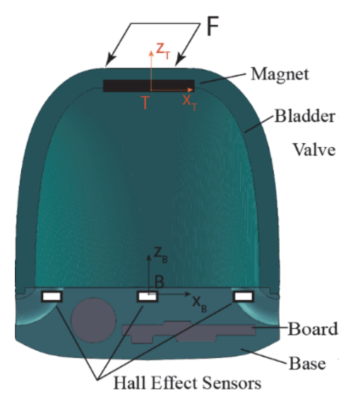
- Soft-Robotic bladders are placed inbetween the headform and headshell
- Each bladder consists of a compressible air chamber and valve to control flow
- A PCB is embedded into the base of each bladder and senses the position of a magnet in the top of the bladder, and the pressure inside the chamber.
- A machine learning algorithm then fuses the 1D hall effect sensor data to generate a 3D estimation of the bladder state. This then can feed an FEA algorithm to estimate force.

Position Sensing
To obtain an accurate impact estimation on the helmet, each bladder keeps track of the position of its top. This position is useful for mechanical models that can translate this displacement into a force applied on each bladder. With forces known on each bladder, the overall action of the helmet can be determined.
The challenge is how to track this position. In theory, rangefinders such as ultrasonic or infra-red should do the job with simplicity, but in practice we found both of these methods too innacurate when embedded in the bladder base. We decided to try a less conventional method: 3D hall effect sensing.
The theory of operation is simple, a magnet is attached to the top of each bladder. An array of 1D hall effect sensors sense the strength of the magnet at different locations along the plane of the circuit board. As the magnet moves laterally, the strength increases on some sensors, and decreases on others. This information is sent to a neural network that has a model of the system, and outputs a 3D position.
3D Hall Sensing Optimization
Our Contribution: The magnetic model of these systems is difficult to model, and as such we utilized a machine learning algorithm to abstract away the need for a closed-form solution. The new challenge is how to optimize these sensors to get the best accuracy for a given set of electronics and space. No solution that we could find tackled this challenge, and so we wrote a paper that proposes a simulation-based technique.
EE Milestone 1
For the electrical engineering portion of the project, milestone 1 included the designing of test circuit boards for the hall sensor optimization work, and the final paper submission as shown above. To see a presentation on these achievements, see the video below.
Sensor Optimization Test Hardware
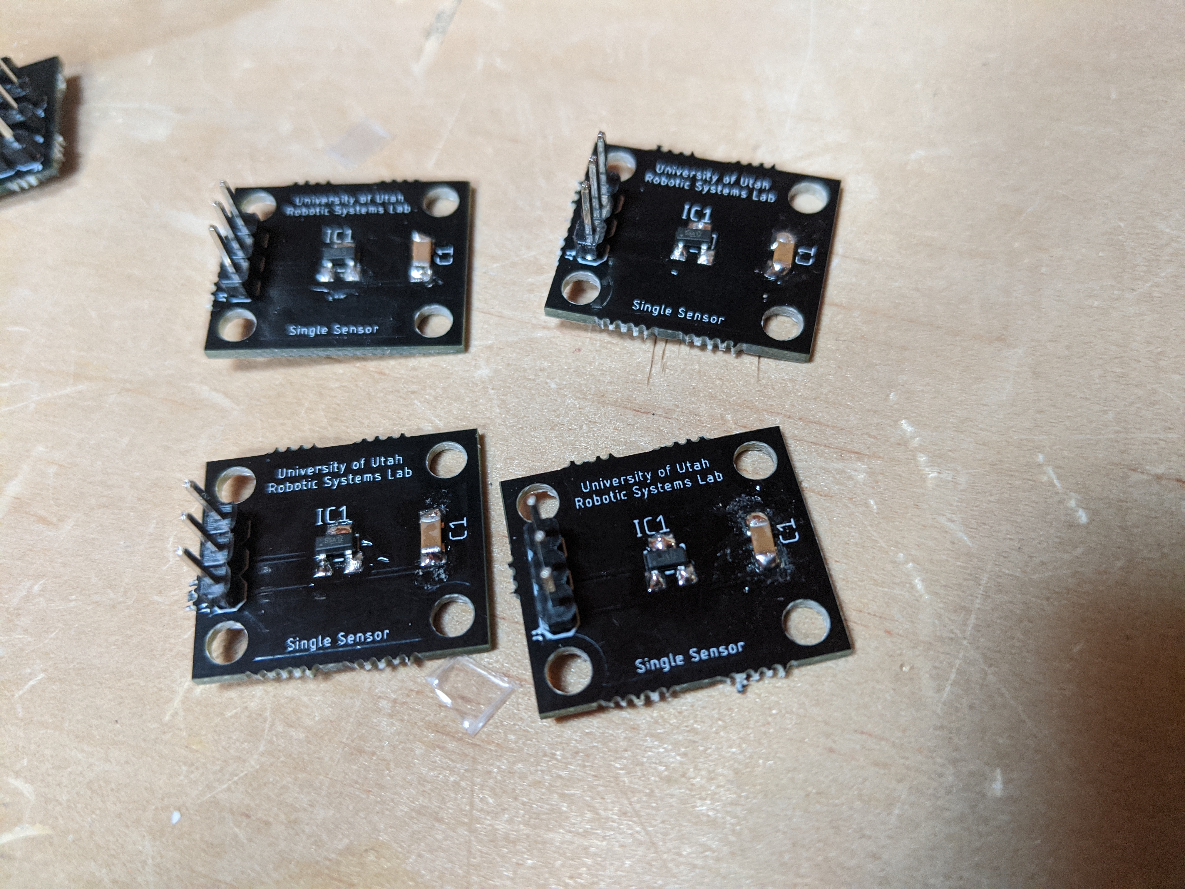
In order to examine the effects of varying hall sensor array positioning, amplification, and magnet types, I created a series of circuit boards.
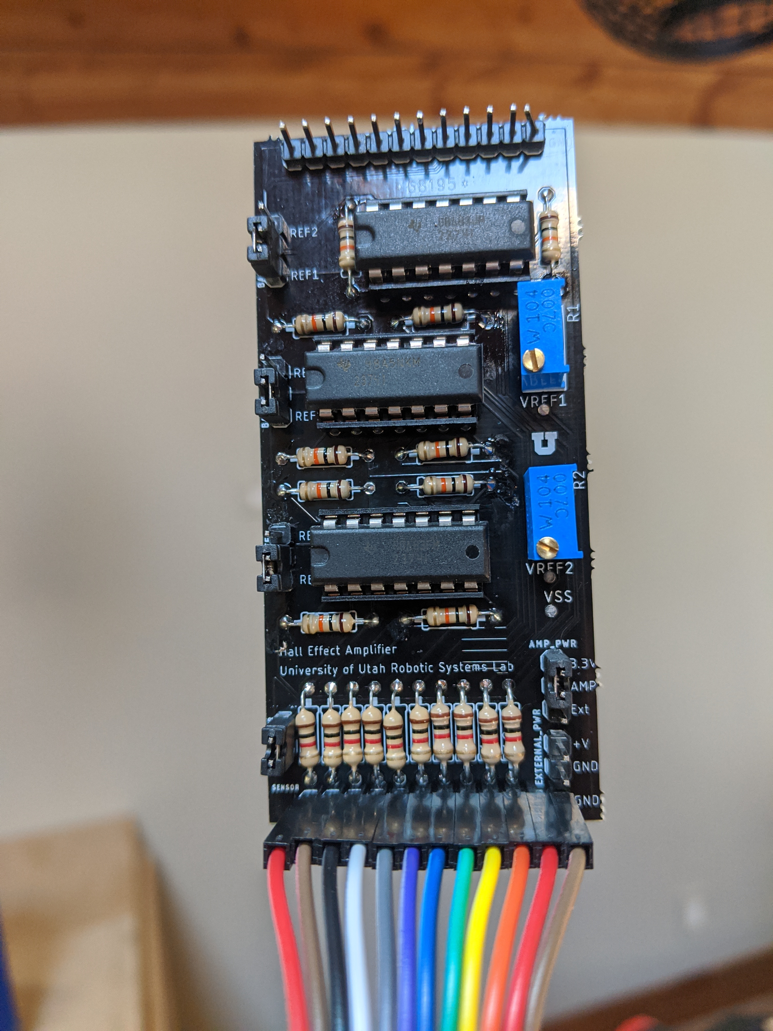
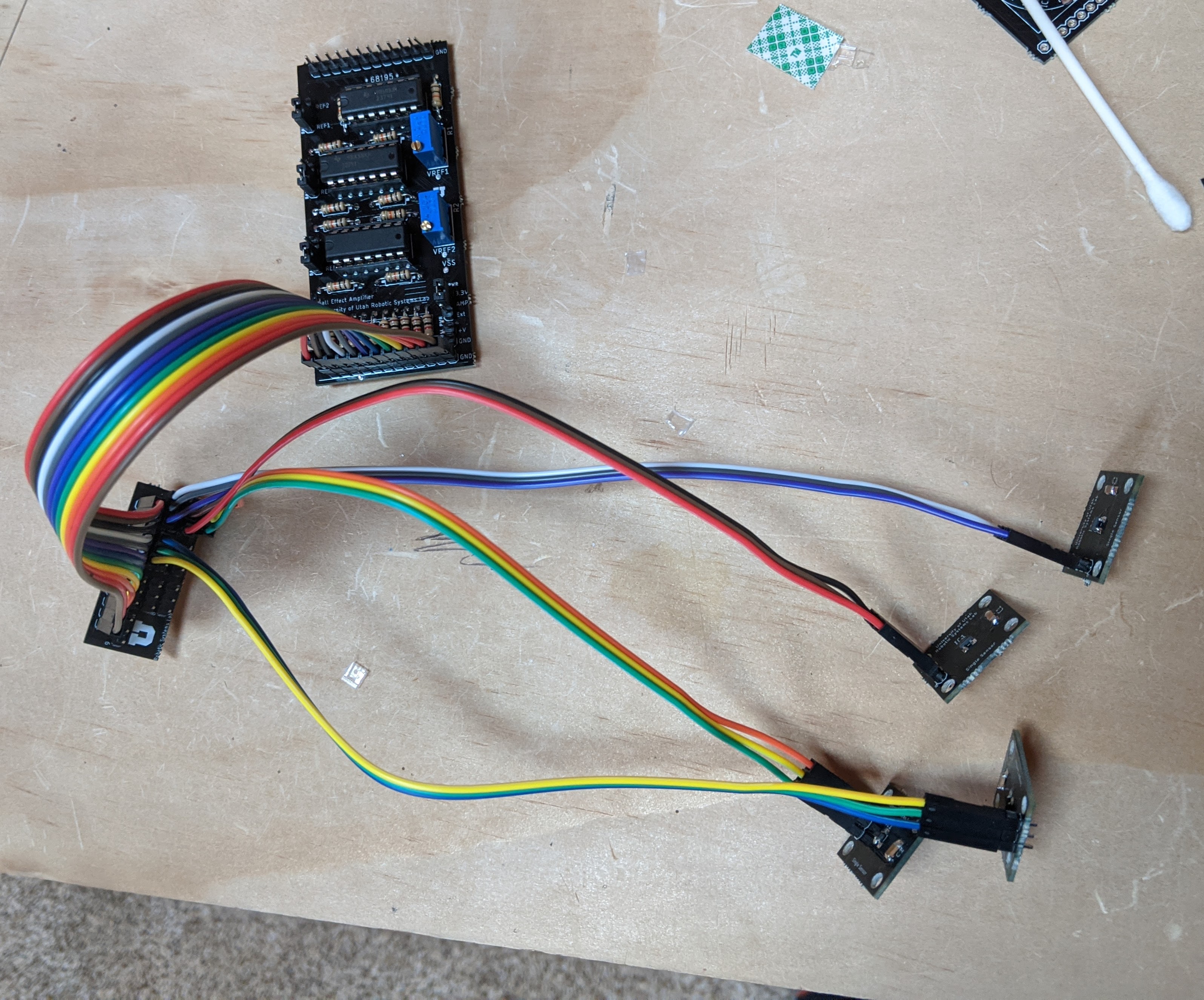
- One of these was an amplifier, that had selectable differential voltage sources, and 10 channels of filtered amplification available.
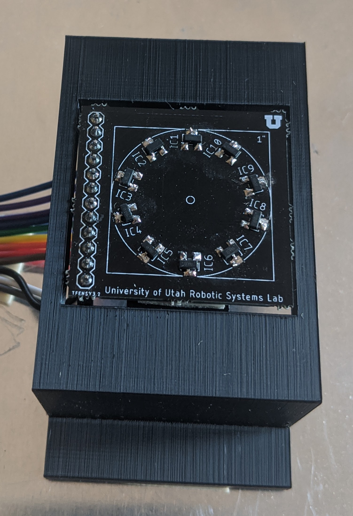
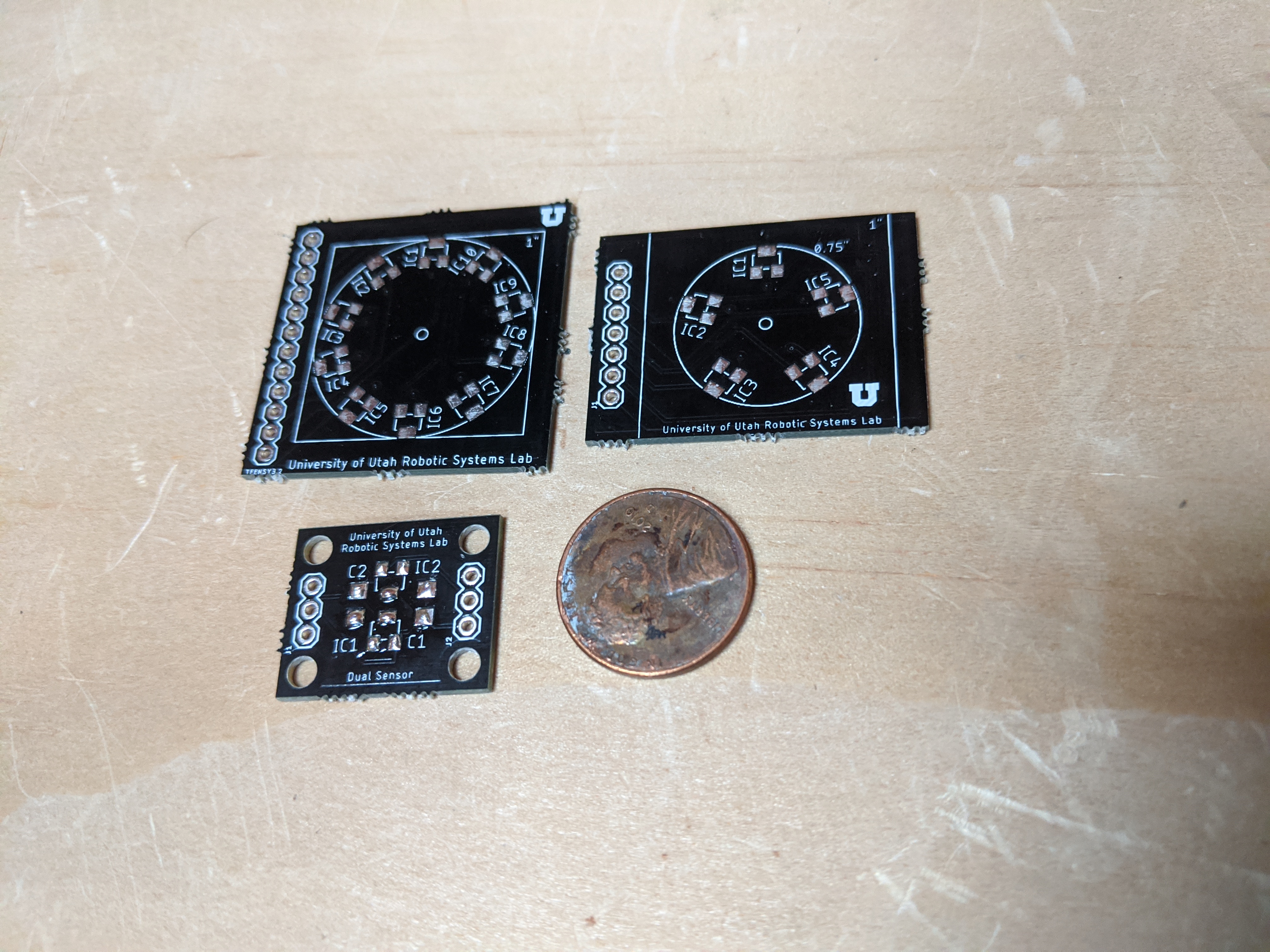
- Another set of these consisted of hall ensors arrayed in different known patterns from five sensors up to ten sensors.
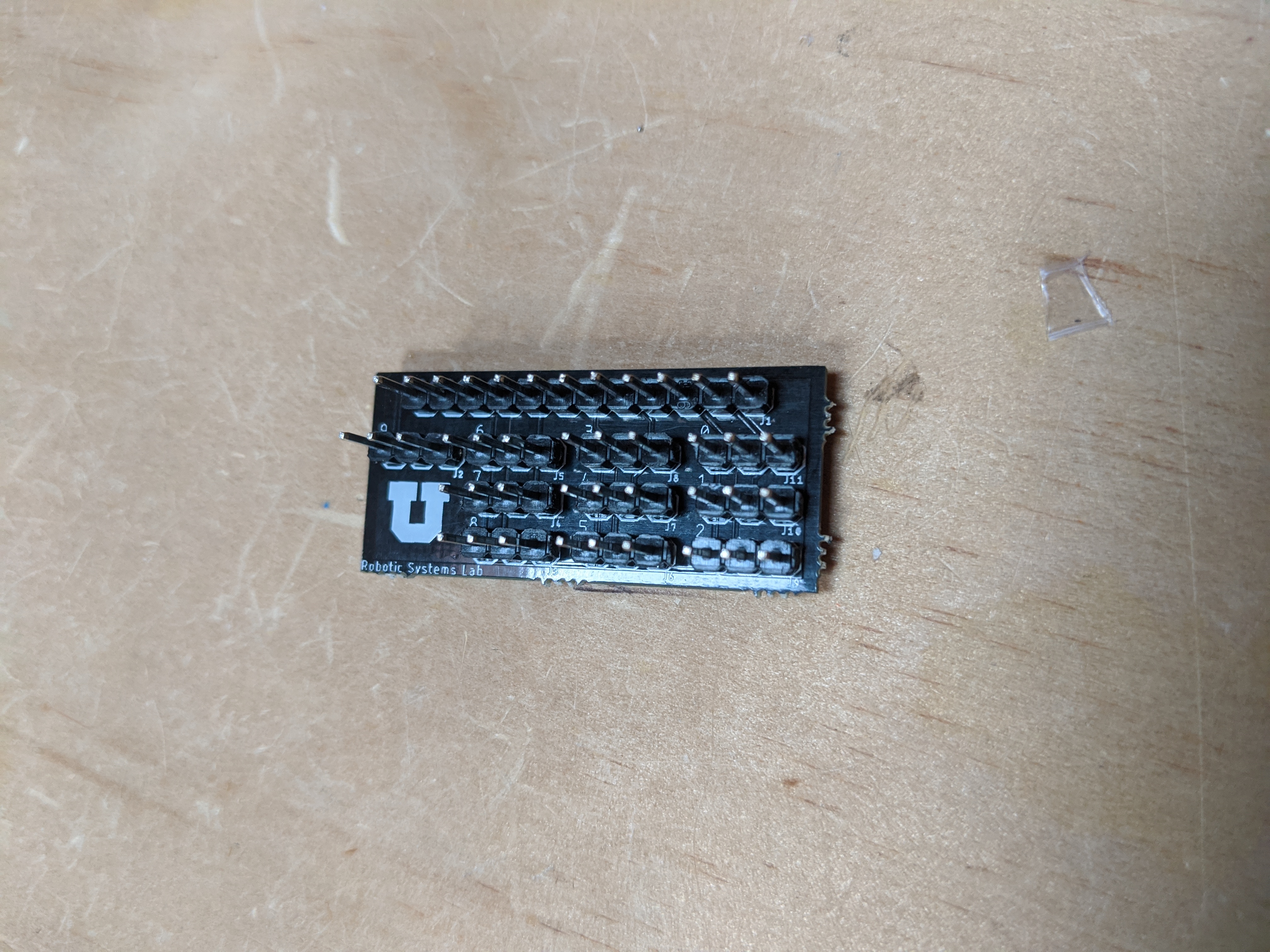
- Finally, I created single sensor and double sensor boards that could be mounted in large areas that a single board could not economically cover. These connected through an aggregation board, and to the amplifier.
- All boards were panelized by myself into a single 10x10cm file that could be manufactured extremely cheaply.
EE Milestone 2
Milestone 2 focused on developing hardware for integration testing in bladders. By comparison, milestone 1 was conducted almost exclusively on a test bench instead of in silicon. To see a presentation on these achievements, see the video below.
EE Milestone 3
Milestone 3 focused on the manufacturing and assembly of the integration test hardware designed in milestone 2. It also focuses on some of the failures encountered, and subsequent fixes.
CE Hardware Prototype
The computer engineering portion of this project is focused on the microcontroller development and integration with the existing sensor hardware. The initial prototype will consist of integrating an existing MCU with a development ADC board. This analog to digital converter will be interfaced with the hardware shown in EE Milestone 3, and functionality of the sensor suite can be demonstrated using an embedded system.
Next Steps & Timetable
February to March ‘21: Assemble and test embedded sensor test bed- April to May ‘21: Evaluate accuracy of embedded system, estimate forces using FEA in real time
- Summer ‘21: Design final hardware with MCU system in bladder
Team Member Roles
- Dr. Mark Minor: Project Director, Robotic Systems Lab Director, Advisor
- Jon Aston: Graduate Student head of project
- Ebsa Eshete: Undergraduate Research Assistant
- Takara Troung: Undergraduate Research Assistant / Project Alumnus